xgoduck_hardware README

README проекта с github.com/LuwuDynamics/xgoduck_hardware. Одним файлом markdown: README.md.

Join our Discord

XGO-Duck

English · 简体中文

Board charging and troubleshooting: English · 简体中文.

Build a robot duck. Explore how it moves. Make it your own.

A 3D-printable biped robot built around Arduino UNO Q and 15 serial servos.

Assembly guide · Bill of materials · Runtime · Training

A duck-shaped biped robot performing a somersault in a looping animation

A clean somersault · CyberBionic Maker

Meet XGO-Duck

XGO-Duck is a duck-shaped biped robot adapted by Luwu Dynamics from Pollen Robotics' Microduck. It combines a printable structure, fifteen Feetech 1910 servos, an Arduino UNO Q, and a custom expansion board with an IMU and servo interfaces.

This repository is the hardware starting point: print the parts, prepare the electronics, and assemble the robot. Companion repositories provide the onboard runtime and reinforcement-learning tools, connecting a physical build with motion experiments.

Build Run Experiment
Print the body, legs, neck, head and soft parts. Assemble with the illustrated guide. Configure and calibrate the robot through the companion runtime's browser interface. Study the simulation, train policies and explore your own motions.
Hardware files Onboard runtime RL tools

A closer look

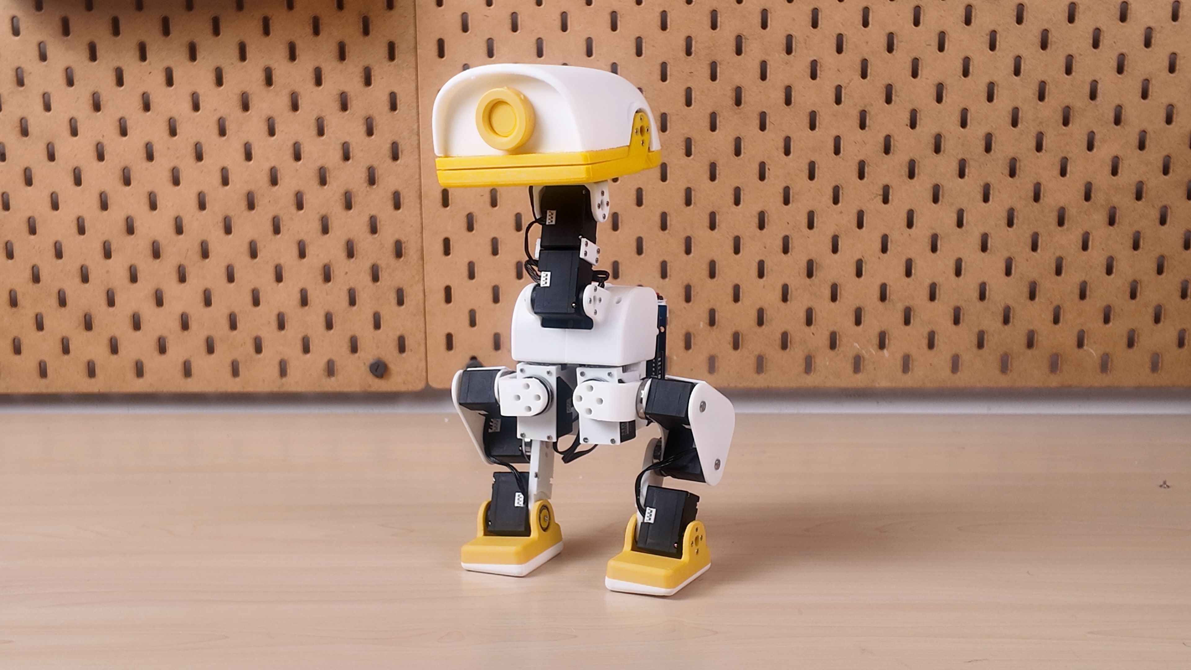
XGO-Duck standing on a workbench, with a white printed body, yellow beak and feet, and exposed leg joints

XGO-Duck prototype — printed parts, articulated legs, and a movable head and beak.

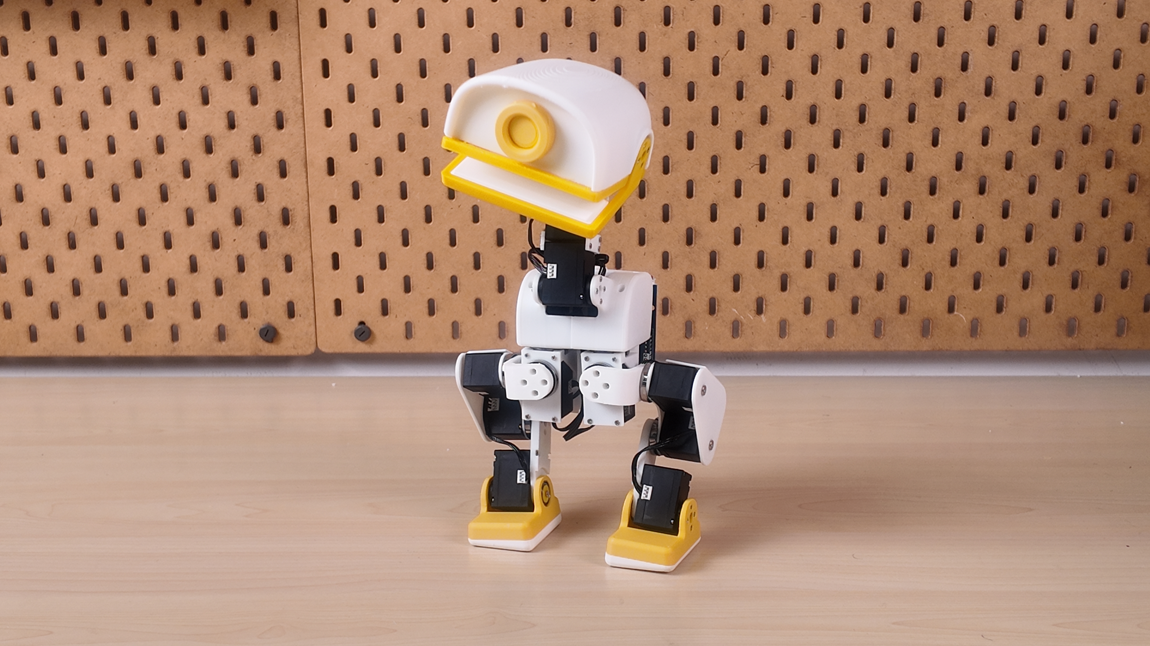
Front view of XGO-Duck with its beak open
A movable head and beak
Four neck/head joints and a separate mouth servo.
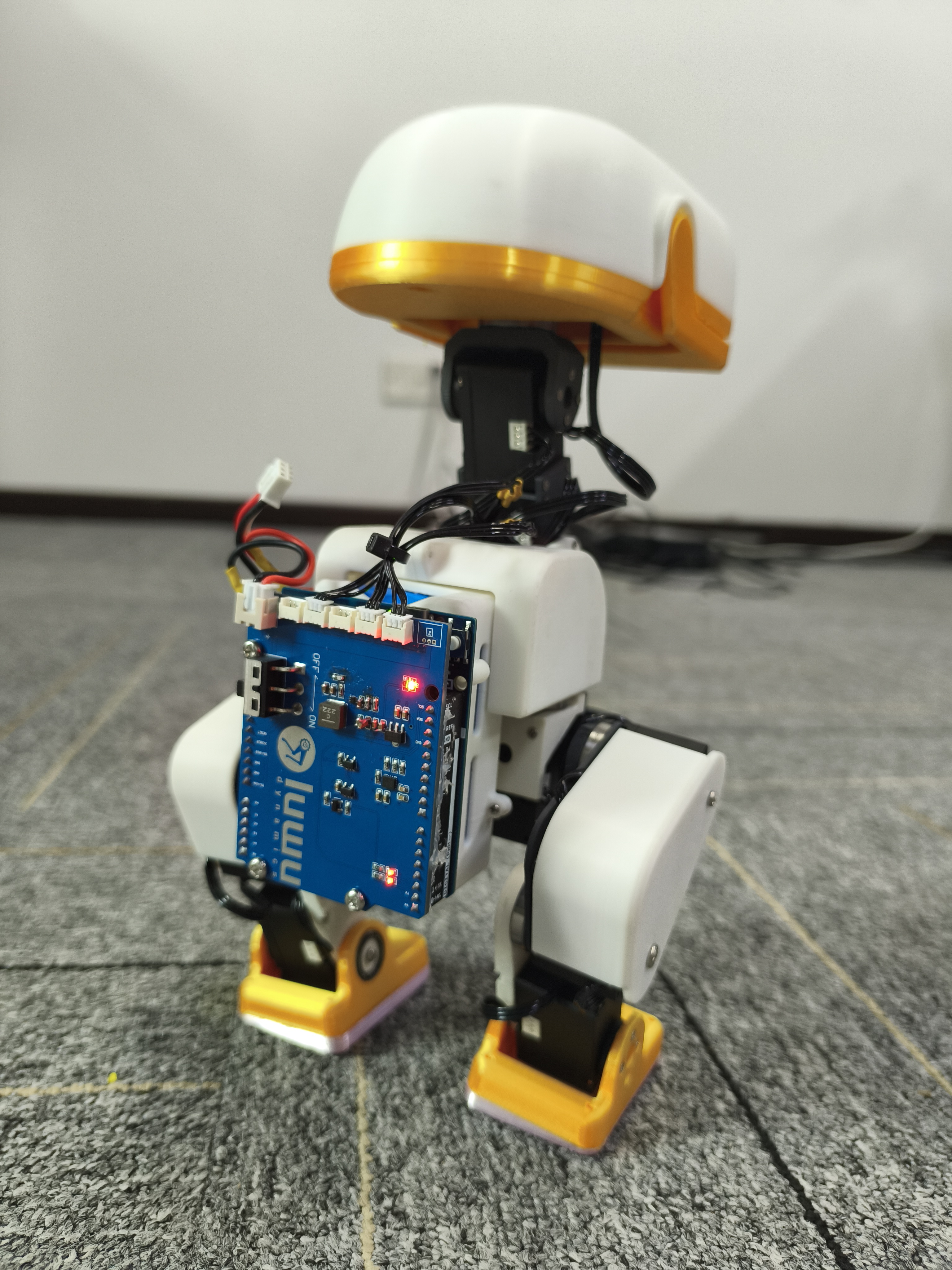
Rear prototype view showing the blue expansion board and servo wiring
Electronics you can inspect
Rear-mounted controller stack and accessible wiring.

The photos show project prototypes. Follow the assembly guide and matching board files for your build revision.

Hardware at a glance

Subsystem What it uses Role
Controller Arduino UNO Q Linux host for policy inference and web UI; STM32 MCU for servo and sensor communication
Actuation 15 Feetech 1910 serial servos 10 leg joints, 4 neck/head joints, and 1 mouth joint
Expansion board Luwu UNO Q expansion board Power distribution, servo connections and IMU integration
Motion sensing QMI8658A 6-axis IMU Acceleration and angular-velocity feedback
Structure STL parts Body, leg, neck and head components
Soft parts TPU-designated STL files Foot soles and mouth parts

The motion policy outputs targets for 14 joints; the mouth servo is controlled separately. Component details and purchasing checks are collected in the BOM notes.

How the system connects

flowchart TD
    UI[Browser: setup, calibration and control] <--> HOST[UNO Q Linux: ONNX policy and web UI]
    RL[Training computer: simulation and RL] -->|Export ONNX policy| HOST
    HOST <-->|Arduino Bridge| MCU[UNO Q STM32: servo and IMU loop]
    MCU <-->|Serial bus| SERVOS[15 Feetech 1910 servos]
    IMU[QMI8658A IMU] -->|Sensor feedback| MCU
    BOARD[Custom expansion board] --- SERVOS
    BOARD --- IMU

This is a functional overview; use the board design and assembly documentation for electrical connections.

Start your build

Current board version: V1.1 (2026-10-26). Use the V1.1 design and production files. Previous files and wiring instructions are archived separately.

1. Prepare parts and electronics

Open the bill of materials for the robot purchasing list, supplier links and battery requirements, and PCBA/ for the expansion-board files. The robot BOM and PCB manufacturing BOM serve different purposes: a finished expansion board already includes its board-level components.

Part Quantity
Arduino UNO Q (2 GB / 4 GB) 1
Robot expansion board — Luwu Dynamics Store 1
Feetech 1910 servo with AMP 3-pin cable 15
Battery pack, listed as “18650 battery 8.4V” 1
8.4 V Li-ion battery charger with 5.5 × 2.1 mm DC barrel plug (DC5521) 1
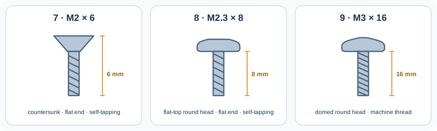
M2 × 6 countersunk, flat-end self-tapping screw 204 (200+4 for roller)
M2.3 × 8 flat-top round-head, flat-end self-tapping screw 6
M3 × 16 round-head machine screw 4
10 × 15 × 3 mm bearing 11 (3+8 for roller)
16 × 22 × 4 mm bearing 11

Quantities include the optional roller skates: 4 additional M2 × 6 screws and 8 additional 10 × 15 × 3 mm bearings. Confirm the pack, charger, connector polarity and power requirements using the component notes before sourcing or powering the build.

The expansion-board store page also offers a separate battery-and-charger option. Select Only Robot Driver Board for Arduino UNO Q for the board above; the bundle has not been verified against the battery and charger specifications in this list. See the purchasing notes.

For easier purchasing, Luwu Dynamics offers an official XGO-Duck electronics kit containing all components in the BOM except the Arduino UNO Q.

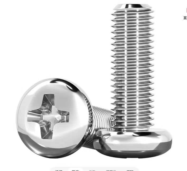
Identify the three fasteners before ordering. Items 7 and 8 are self-tapping screws with flat ends. Items 8 and 9 share the same rounded side profile; item 8 has a flat top, while item 9 has the gently domed top shown in the photo below and a machine thread. The following shape guide is illustrative. See the product photo and size references in the BOM.

Shape guide for the M2 by 6 countersunk flat-end self-tapping screw, M2.3 by 8 flat-top round-head flat-end self-tapping screw, and M3 by 16 domed round-head machine screw Reference photo of the intended shallow, gently domed round screw head for item 9 only

Item 9 has the domed top shown here. Item 8 has the same rounded sides but a flat top. The photo is a head-style reference, not a size or thread specification.

2. Print the structure

Complete 3MF print projects

Choose V5 for the audio/video design or V2 for the original design. Each project bundles the model parts, prepared plate layouts, and saved print settings, so you do not need to download and arrange individual STL files.

Robot version Complete print project
V5 — Audio/video design Download V5 3MF
V2 — Original design Download V2 3MF

Open the matching project in Bambu Studio, confirm your printer and PLA/TPU assignments, then slice and print. Both projects save a P1P / 0.4 mm nozzle profile and nine plates. Choose one V1/V1.1 board enclosure; roller-skate parts are optional. These are project files, not pre-sliced G-code.

Plate guide and instructions · 简体中文

Individual STL files

Choose the folder for your kit. Both sets were exported from the corresponding 3MF project, with each part positioned individually on the build plane. The filename prefix identifies the kit even when a file is downloaded separately.

Kit and folder STL files Filename prefix
V2 — Standard kit, without audio/video 47 V2_STANDARD_
V5 — Audio/video kit 50 V5_AUDIO_VIDEO_

Each folder includes English and Chinese instructions. Numbered files such as _01 and _02 already represent separate instances: print each selected file once, without multiplying it again by a retained 2x or 4x label. Parts marked TPU require flexible material. Keep the parts for your chosen version together and select one backpack enclosure for your board revision.

Use the print inventory to track parts. Test a servo mount and bearing fit before printing the full set; a complete validated print profile is still to be documented.

The optional roller-skate parts are already included in each version folder: two numbered tire supports, four tires and four tire axes. Print each of those files once when using that accessory. The structure/ directory contains only the V2_STANDARD_/ and V5_AUDIO_VIDEO_/ sets.

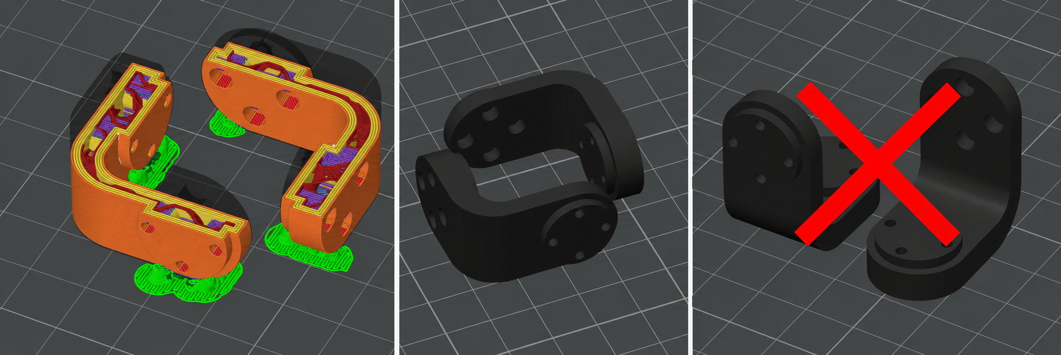
Print orientation reference: slicing preview on the left, recommended placement in the center, and incorrect placement marked with a red cross on the right

Print orientation matters: place the part as shown before slicing — lay it flat with the open channel facing up and the two end tabs resting firmly on the build plate. Use 4 walls and 13% Gyroid infill. Do not stand it upright, lay it on its side, or flip it over, and do not rely on the slicer's auto-arrange. Otherwise the holes may deform and the ends may break. After slicing, check the preview against the reference image before printing.

3. Configure servos and assemble

Prepare each servo's ID and center position using the runtime setup instructions, then follow Assembly_Guide.pdf.

Assembly reference Focus
Page 1 Servo ID placement
Pages 2–5 Shaft preparation, initial structure and cable routing
Pages 6–15 Legs, feet and soles
Pages 16–23 Head and neck mechanisms
Pages 24–25 Final assembly

The build guide adds preparation and inspection checkpoints. Configure one servo at a time, label its ID, and leave cable clearance through each joint's movement.

4. Calibrate and bring it to life

Install the onboard runtime, verify servo and IMU feedback, and complete calibration with the robot supported. Start with the default pose before motion trials.

The runtime includes walk, get-up and pick policies, plus separate mouth control. Their behavior depends on the assembled hardware, calibration and test conditions. Using the bundled policies does not require training a new model.

Hardware files

Path Contents
Assembly_Guide.pdf 25-page illustrated assembly reference
BOM.md Whole-robot purchasing list, supplier links and battery reference image
structure/V2_STANDARD_/ · structure/V5_AUDIO_VIDEO_/ Separate standard and audio/video STL sets, with bilingual guides
V1.1 schematic Altium schematic source
V1.1 BOM · Placement data Board materials and placement coordinates
V1.1 production files Fabrication notes, Gerber and drill files
V1.1 silkscreen layout PDF reference
V1.1 DWG · STEP model Drawing and 3D model
Previous version archive Complete previous files and historical instructions
docs/ Build, printing, BOM and troubleshooting notes

From hardware to your own behavior

Repository Purpose
xgoduck_hardware Mechanical parts, electronics, BOM and assembly
xgoduck_runtime_arduino UNO Q firmware, policy execution, browser setup and control
xgoduck_rl Simulation, reinforcement-learning training and policy export

Keep the hardware, runtime and policy revisions together in your build record. This makes it easier to reproduce a working configuration and diagnose changes.

Origins and contributions

XGO-Duck builds on Microduck and microduck_rl by Pollen Robotics. The duck form, 15-servo arrangement and policy joint order originate in that work. Luwu Dynamics' adaptation focuses on Arduino UNO Q, Feetech 1910 servos, the custom expansion board, and the matching software/model integration. See origins and adaptations.

Build reports, tested print settings, clearer assembly photos and reproducible fixes are welcome. Read CONTRIBUTING.md or open an issue.

For reuse terms, consult LICENSING.md and the applicable file-level notices. Contact: [email protected].

xgoduck_hardware (LuwuDynamics/xgoduck_hardware)

Ищем в базе…

Что это такое?XGO-Duck — это напечатанный на 3D-принтере двуногий робот-утка. Этот репозиторий — отправная точка для аппаратной части: STL-модели конструкции, файлы PCB/Altium для самодельной платы расширения, список материалов и иллюстрированное руководство по сборке.
Как мне на самом деле собрать утку?Закажите детали из BOM, напечатайте STL-модели из structure/ (следуя правилам именования файлов и ориентации при печати), соберите утку по руководству AssemblyGuide.pdf на 25 страниц, затем задайте ID и центры сервоприводов и откалибруйте робота через сопутствующую бортовую программную среду.
Какие детали и инструменты нужно купить?Arduino UNO Q, плату расширения от Luwu Dynamics, 15 последовательных сервоприводов Feetech 1910, аккумуляторный блок Li-ion на 8,4 В с зарядным устройством, набор винтов и подшипников, а также доступ к 3D-принтеру. Luwu продаёт набор электроники, в который входит всё, кроме самой Arduino UNO Q.
На что стоит обратить внимание при сборке?В более ранней партии печатных плат расширения перепутаны GND и SIGNAL на трёх разъёмах; владельцам таких плат нужно выполнить особое исправление проводки для старой версии. Ориентация деталей при печати критична, иначе отверстия деформируются. Полностью проверенного профиля печати пока нет в документации.
Где находится программа управления движением?Её нет в этом репозитории: исполнение политик и браузерный интерфейс настройки находятся в сопутствующем репозитории 'xgoduckruntimearduino', а инструменты симуляции и обучения с подкреплением — в 'xgoduckrl'. Этот репозиторий охватывает только физическое железо.
Что такое Microduck?XGO-Duck — адаптация проекта Microduck с открытым исходным кодом от Pollen Robotics, выполненная компанией Luwu Dynamics. Она использует форму утки, схему расположения 15 сервоприводов и порядок суставов политики из оригинала, но заменяет их на Arduino UNO Q и сервоприводы Feetech 1910.
Нужно ли обучать собственную модель ИИ, чтобы утка ходила?Нет. Сопутствующая программная среда поставляется с готовыми политиками ходьбы, вставания, захвата и управления ртом, так что для использования встроенных поведений ничего обучать самостоятельно не нужно.
Что делает IMU на плате?Шестиосевой IMU QMI8658A, установленный на плате расширения, передаёт данные об ускорении и угловой скорости, которые используются для баланса и управления движением.
Какие есть похожие проекты?Microduck-build-tutorial, Dummy-Robot, Embodied-AI-Guide, microduck-replica, Marlin, oomwoo, copper-rs, jumper
Автор
LuwuDynamics
Размер
146.6 MB
Звёзды
2K
Обновлён
КоммитNov 13
Возраст
1 мес
Коммиты · 90 дней