



这是什么?
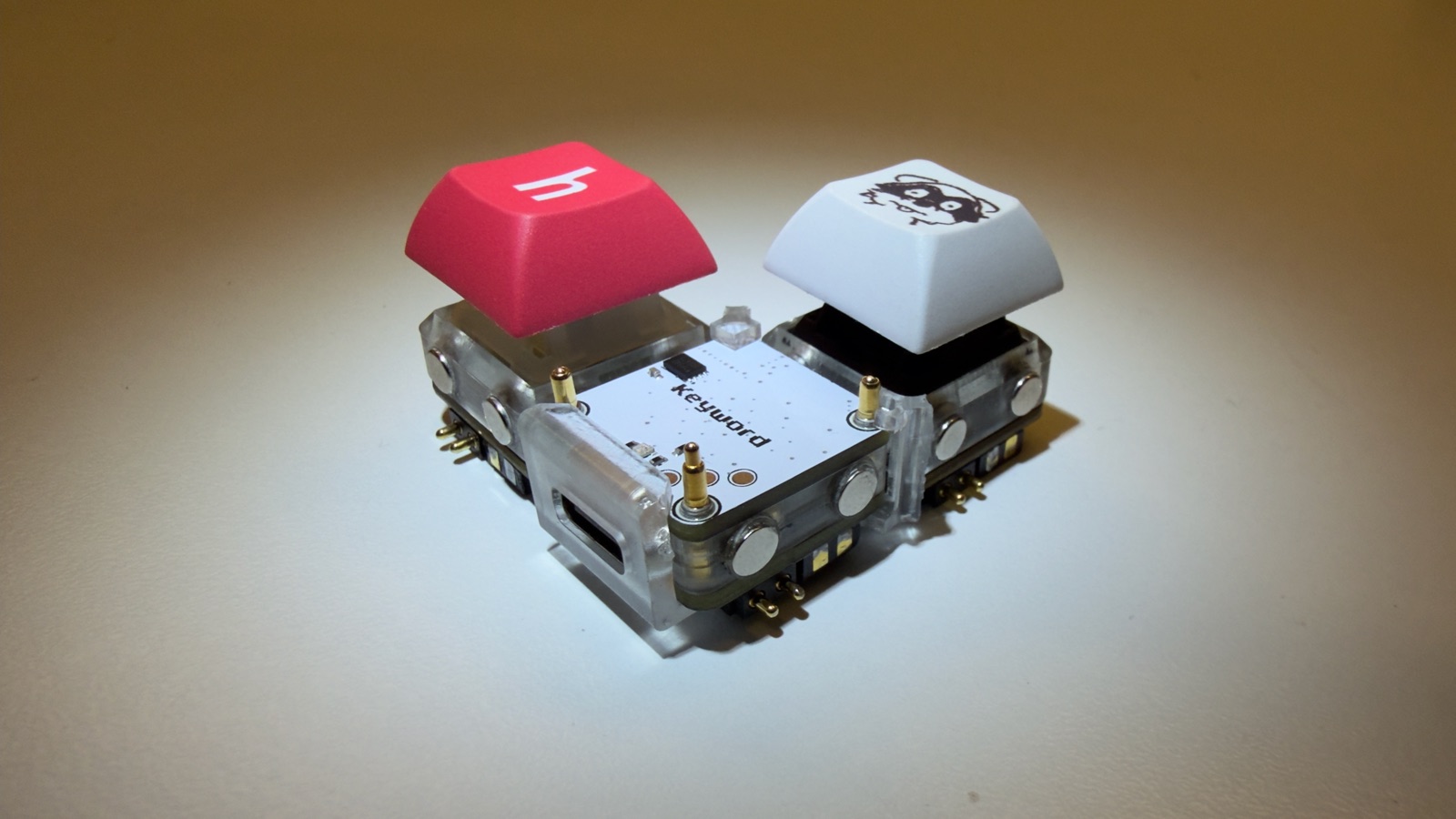
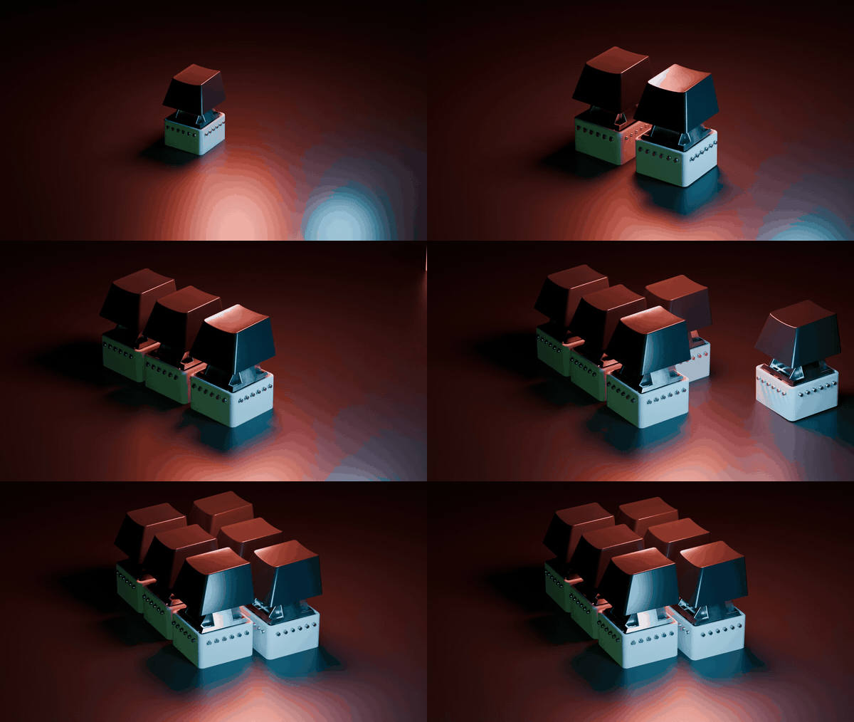
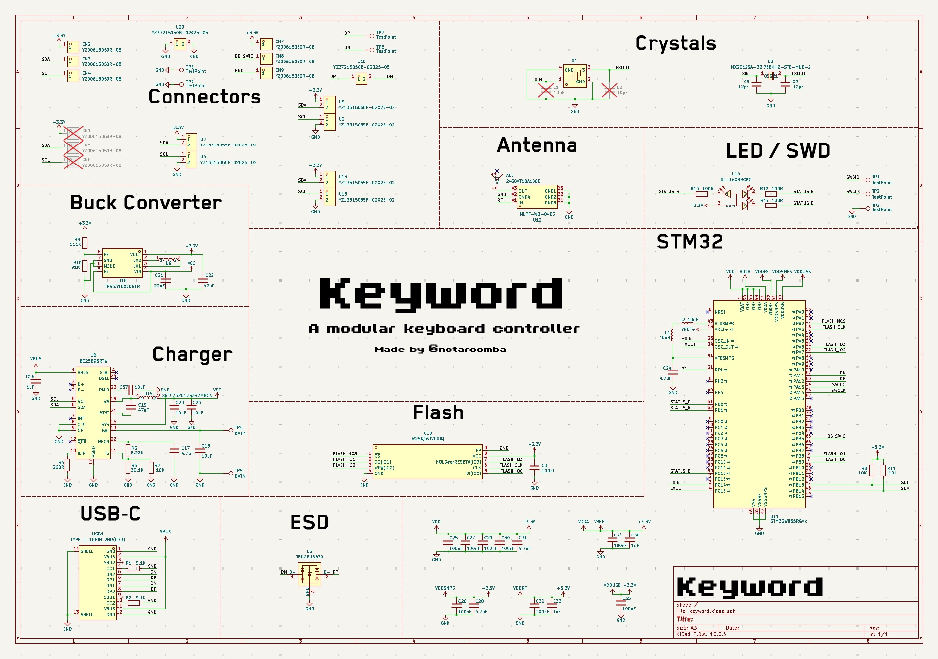
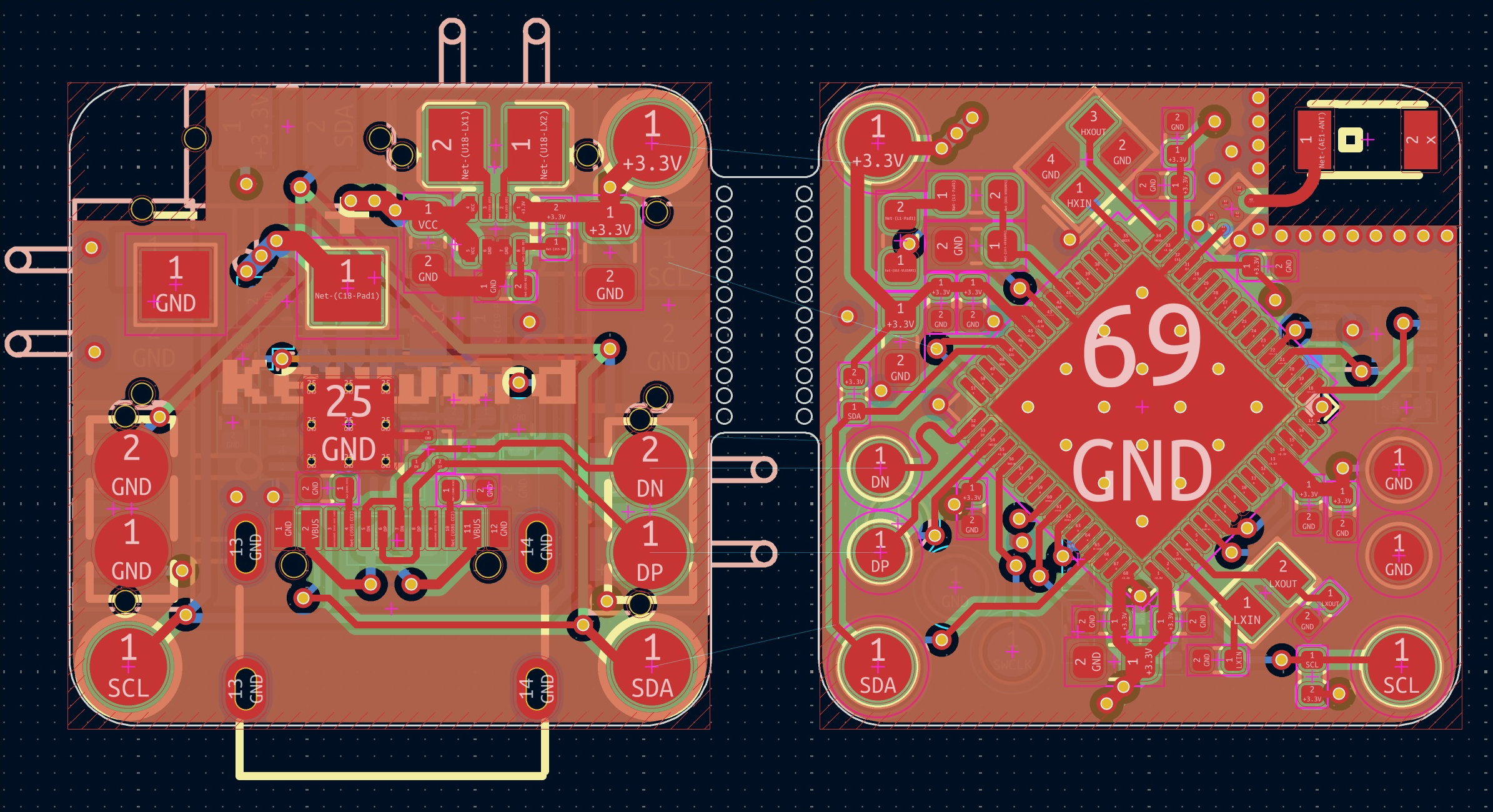
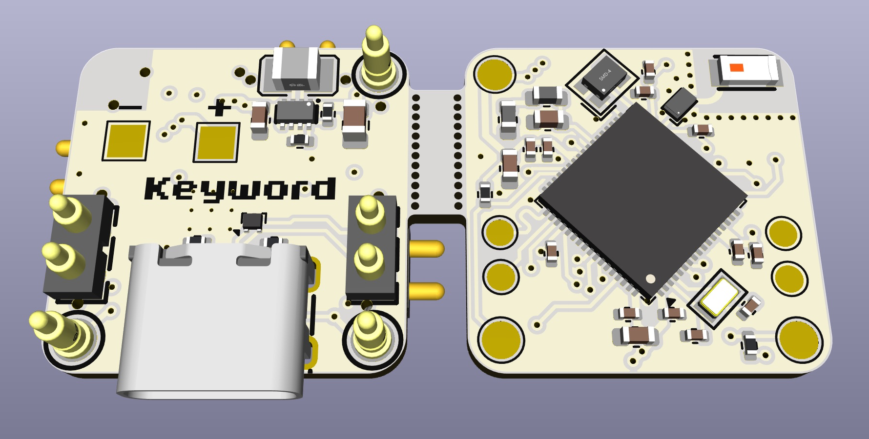
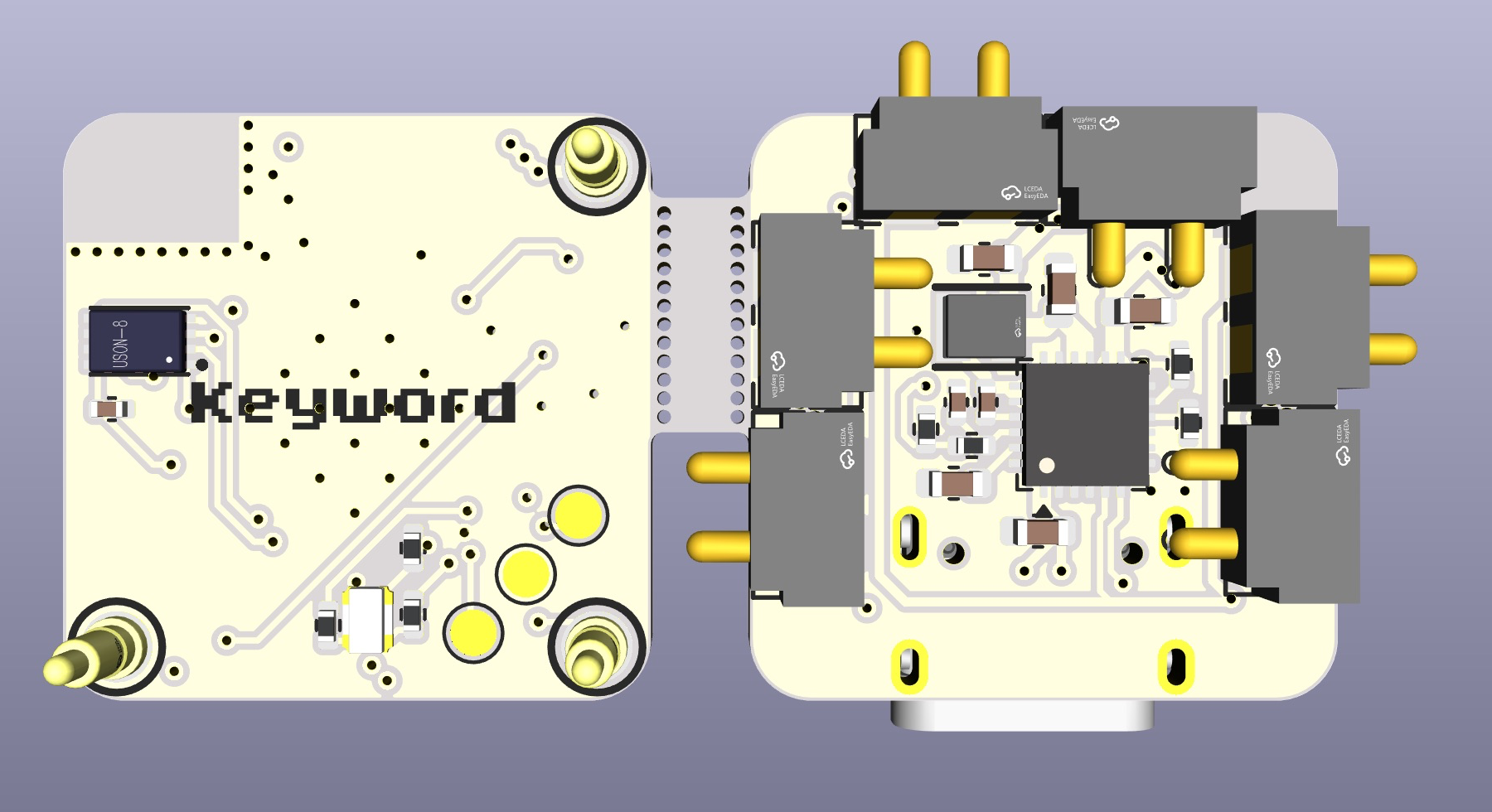
 Keybytes 是一款开源模块化机械键盘,每个按键都是一块可更换的小型 PCB(即 Keybit),内置 RISC-V 微控制器,通过 pogo pin 连接,并由磁吸外壳固定在一起,支持蓝牙和 USB。
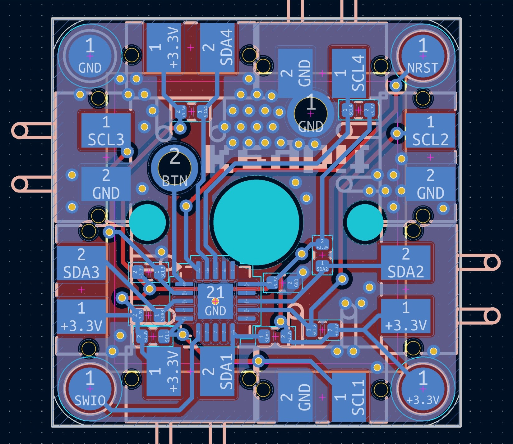
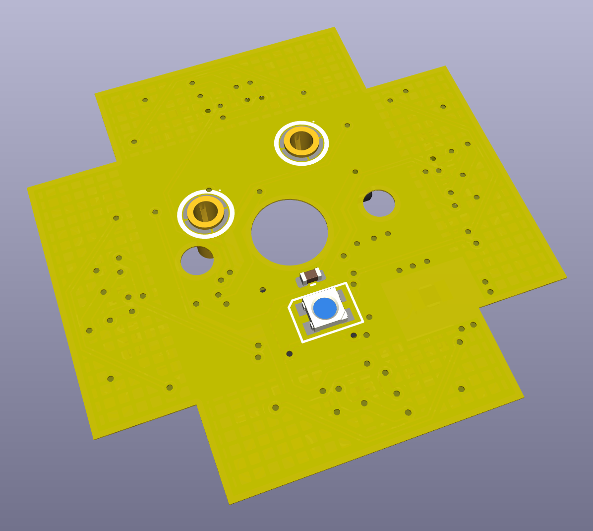
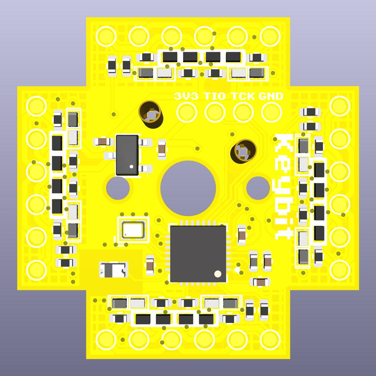
我到底该怎么做一个?从 JLCPCB 等打样服务订购 Keybit 和 Keyword 的 PCB(文件位于仓库中,使用 KiCad 设计);用 cad 文件夹里的 Onshape STEP 文件 3D 打印或切割磁吸外壳;焊接 Cherry MX 轴和 pogo pin,然后通过编程焊盘逐个刷写每个 keybit。
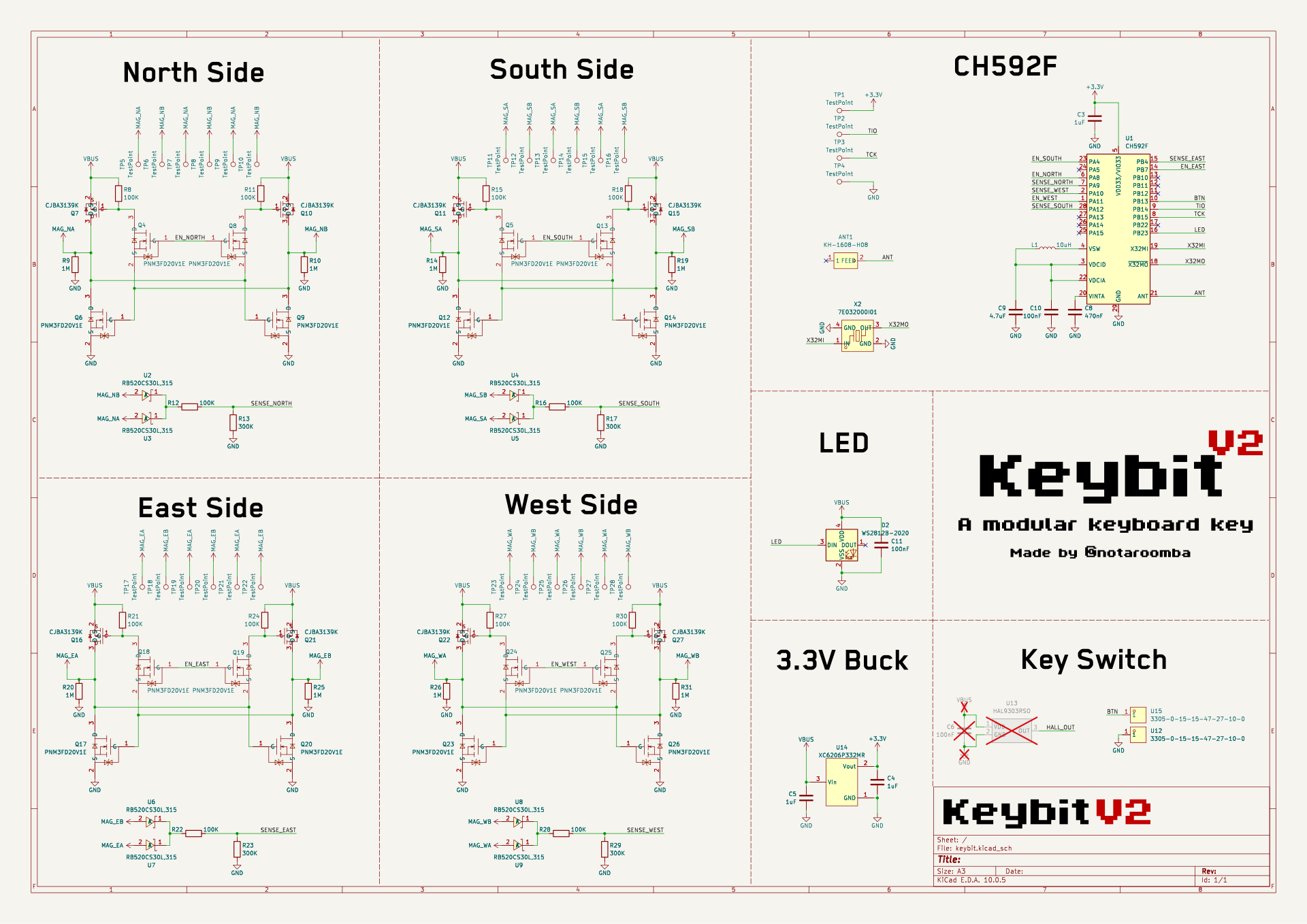
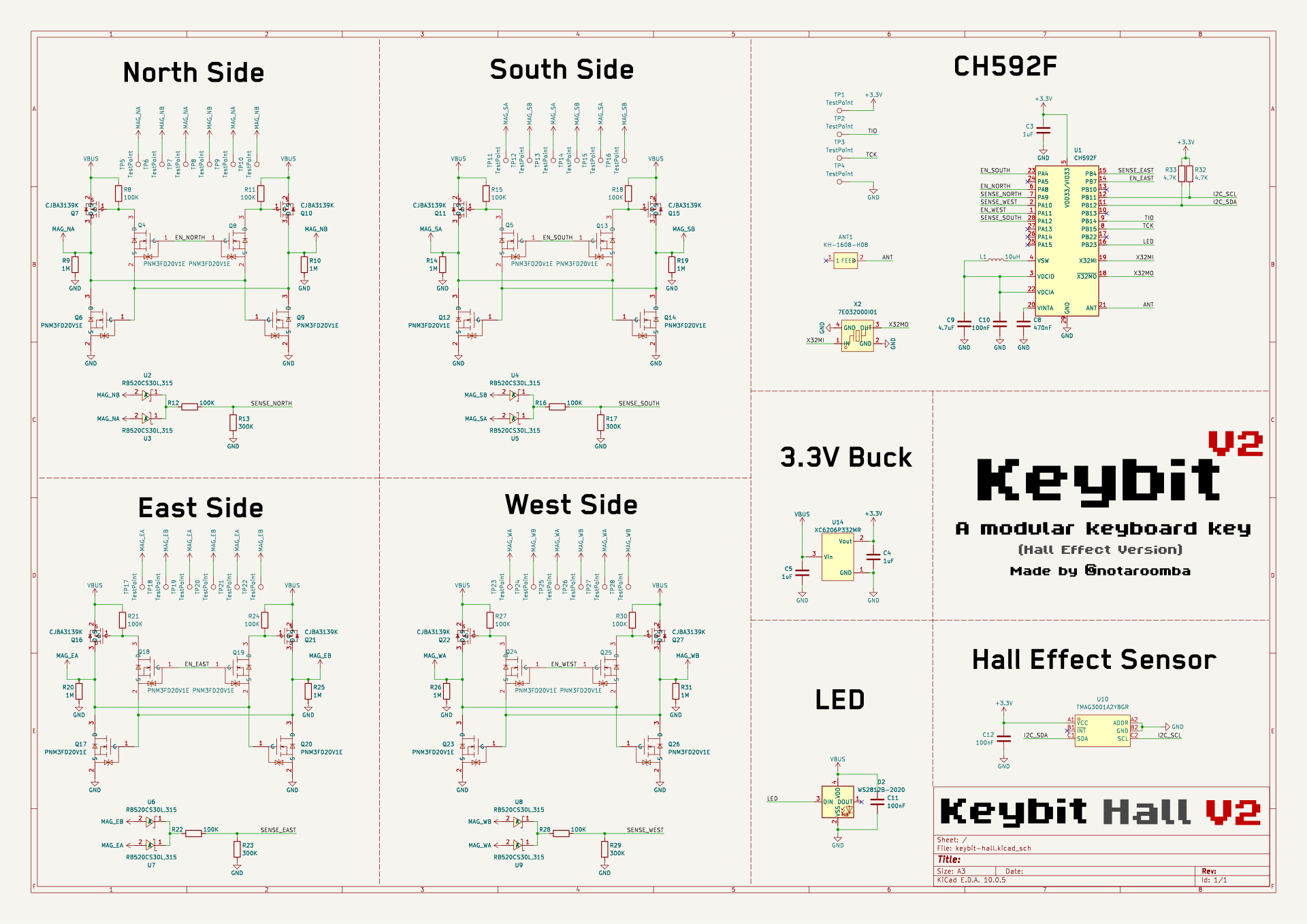
从 JLCPCB 等打样服务订购 Keybit 和 Keyword 的 PCB(文件位于仓库中,使用 KiCad 设计);用 cad 文件夹里的 Onshape STEP 文件 3D 打印或切割磁吸外壳;焊接 Cherry MX 轴和 pogo pin,然后通过编程焊盘逐个刷写每个 keybit。组装这个需要哪些工具和零件?需要 KiCad 来查看或修改 PCB 文件,需要 Onshape 来打开外壳 STEP 文件,需要 STM32CubeMX 来处理主板固件,需要 JLCPCB 等 PCB 打样或贴片服务,还需要基本的焊接技能,因为 Keybit 使用 CH32V003,Keyword 使用 STM32WB55RGV6。
需要 KiCad 来查看或修改 PCB 文件,需要 Onshape 来打开外壳 STEP 文件,需要 STM32CubeMX 来处理主板固件,需要 JLCPCB 等 PCB 打样或贴片服务,还需要基本的焊接技能,因为 Keybit 使用 CH32V003,Keyword 使用 STM32WB55RGV6。重新排列按键能直接用吗?只有每个 keybit 方向正确才行:N/W 两侧的 pogo pin 负责供电和 I2C,如果 keybit 方向装反,它的 SCL 会接到 3.3V、SDA 接到 GND,因此保持不亮。所有 keybit 还必须运行相同的固件版本,否则无法互相通信。
只有每个 keybit 方向正确才行:N/W 两侧的 pogo pin 负责供电和 I2C,如果 keybit 方向装反,它的 SCL 会接到 3.3V、SDA 接到 GND,因此保持不亮。所有 keybit 还必须运行相同的固件版本,否则无法互相通信。keybit 如何与主板以及彼此通信?它们通过四个方向的 pogo pin 使用 I2C 通信。接线设计使得只有当 keybit 与相邻 keybit 或主板 Keyword 正确朝向时,供电、SDA 和 SCL 才会对齐。
它们通过四个方向的 pogo pin 使用 I2C 通信。接线设计使得只有当 keybit 与相邻 keybit 或主板 Keyword 正确朝向时,供电、SDA 和 SCL 才会对齐。每个 keybit 上的状态 LED 是什么意思?白色常亮表示空闲,白色快速闪烁表示已连接到 Keyword,蓝色闪烁表示位于编程引脚上,绿色表示已刷写且为最新版本,红色常亮或红色闪烁则表示更新卡住或 keybit 方向装反。
白色常亮表示空闲,白色快速闪烁表示已连接到 Keyword,蓝色闪烁表示位于编程引脚上,绿色表示已刷写且为最新版本,红色常亮或红色闪烁则表示更新卡住或 keybit 方向装反。如何更新所有 keybit 的固件?Keyword 板保存 keybit 固件。更新 Keyword 后,依次将每个 keybit 放到其编程引脚上,等待绿色 LED 亮起,因为固件版本不匹配的 keybit 无法通信。
Keyword 板保存 keybit 固件。更新 Keyword 后,依次将每个 keybit 放到其编程引脚上,等待绿色 LED 亮起,因为固件版本不匹配的 keybit 无法通信。作者是否还做过类似的开源硬件项目?做过。README 中链接了同一作者的相关项目:Ember,一款支持蓝牙的回流焊热板;Cyberboard,一款 Pico 尺寸的 STM32 开发板;Trace,一把 PCB 尺子;以及 Linea,一款 EMR 平板。
做过。README 中链接了同一作者的相关项目:Ember,一款支持蓝牙的回流焊热板;Cyberboard,一款 Pico 尺寸的 STM32 开发板;Trace,一把 PCB 尺子;以及 Linea,一款 EMR 平板。有哪些类似的项目?InkBoy, esp-sdr, w1700k-sdr, MicroManipulatorStepper, mu300-linux, rt-thread, xgoduck_hardware, unleashed-firmware
InkBoy, esp-sdr, w1700k-sdr, MicroManipulatorStepper, mu300-linux, rt-thread, xgoduck_hardware, unleashed-firmware它属于哪些主题?diy, pcb-design, battery, bluetooth-low-energy, mechanical-engineering, wireless, risc-v, cad, microcontroller, usb, bluetooth, keyboard
diy, pcb-design, battery, bluetooth-low-energy, mechanical-engineering, wireless, risc-v, cad, microcontroller, usb, bluetooth, keyboard