




AERIS-10: Open Source Pulse Linear Frequency Modulated Phased Array Radar





AERIS-10 is an open-source, low-cost 10.5 GHz phased array radar system featuring Pulse Linear Frequency Modulated (LFM) modulation. Available in two versions (3km and 20km range), it's designed for researchers, drone developers, and serious SDR enthusiasts who want to explore and experiment with phased array radar technology.
📡 Overview
The AERIS-10 project aims to democratize radar technology by providing a fully open-source, modular, and hackable radar system. Whether you're a university researcher, a drone startup, or an advanced maker, AERIS-10 offers a platform for experimenting with beamforming, pulse compression, Doppler processing, and target tracking.
🔬 Key Features
- Open Source Hardware & Software - Complete schematics, PCB layouts, firmware, and software available
- Dual Version Availability:
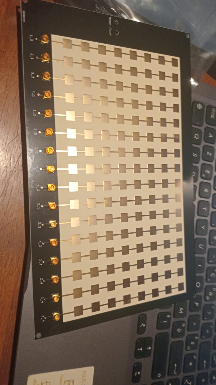
- AERIS-10N (Nexus): 3km range with 8x16 patch antenna array
- AERIS-10E (Extended): 20km range with 32x16 dielectric-filled slotted waveguide array
- Full Electronic Beam Steering - ±45° electronic steering in elevation and azimuth
- Advanced Signal Processing - On-board FPGA handles pulse compression, Doppler FFT, MTI, and CFAR
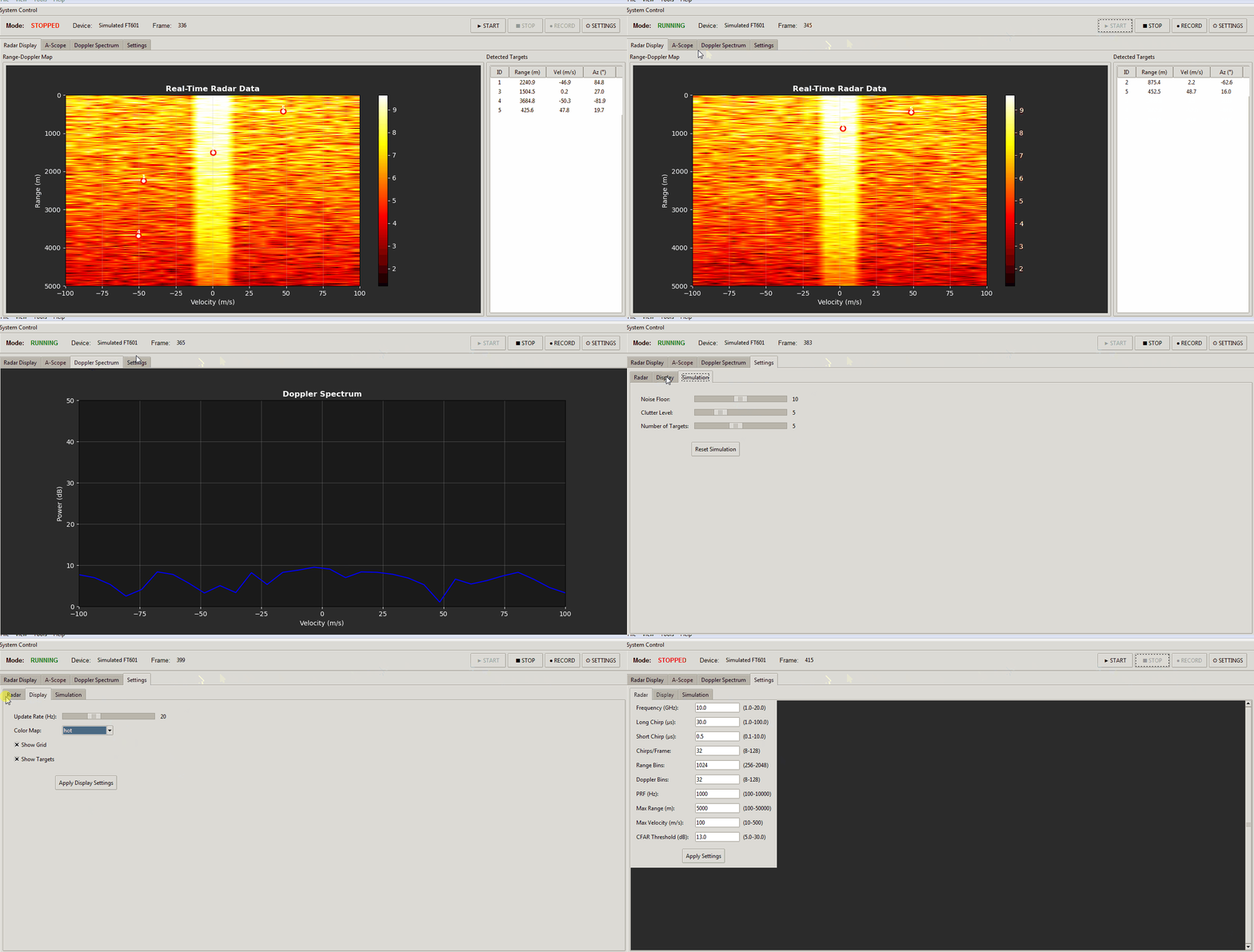
- Python GUI - User-friendly interface with map integration
- GPS/IMU Integration - Real-time position and attitude correction
- Modular Design - Separate power management, frequency synthesis, and RF boards
🏗️ System Architecture
Hardware Components
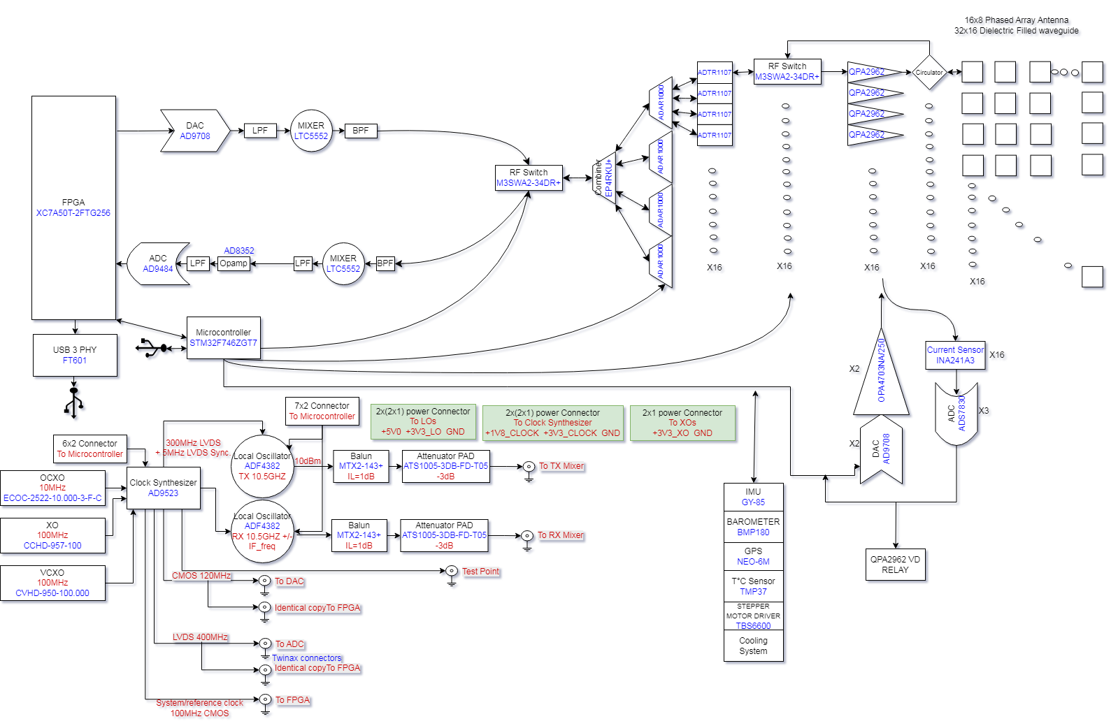
The AERIS-10 main sub-systems are:
Power Management Board - Supplies all necessary voltage levels to the electronics components with proper filtering and sequencing (sequencing ensured by the microcontroller)
Frequency Synthesizer Board - Uses a high-performance Low Jitter Clock Generator (AD9523-1) that supplies phase-aligned clock references for:
- RX and TX Frequency Synthesizers (ADF4382)
- DAC
- ADC
- FPGA
Main Board containing:
- DAC - Generates the RADAR Chirps
- 2x Microwave Mixers (LTC5552) - For up-conversion and IF-down-conversion
- 4x 4-Channel Phase Shifters (ADAR1000) - For RX and TX chain beamforming
- 16x Front End Chips (ADTR1107) - Used for both Low Noise Amplifying (RX) and Power Amplifying (TX) stages
- XC7A50T FPGA - Handles RADAR Signal Processing on the upstream FTG256 board:
- PLFM Chirps generation via the DAC
- Raw ADC data read
- Hybrid Automatic Gain Control (AGC) — cross-layer FPGA/STM32/GUI loop
- I/Q Baseband Down-Conversion
- Decimation
- Filtering
- Forward FFT
- Pulse Compression
- Doppler, MTI and CFAR processing
- USB Interface
- STM32F746xx Microcontroller - Used for:
- Power-up and power-down sequencing (see Power Management Excel File)
- FPGA communication
- Setup and Interface with:
- Clock Generator (AD9523-1)
- 2x Frequency Synthesizers (ADF4382)
- 4x 4-Channel Phase Shifters (ADAR1000) for RADAR pulse sequencing
- 2x ADS7830 8-channel I²C ADCs (Main Board, U88 @ 0x48 / U89 @ 0x4A) for 16x Idq measurement, one per PA channel, each sensed through a 5 mΩ shunt on the PA board and an INA241A3 current-sense amplifier (x50) on the Main Board
- 2x DAC5578 8-channel I²C DACs (Main Board, U7 @ 0x48 / U69 @ 0x49) for 16x Vg control, one per PA channel; closed-loop calibrated at boot to the target Idq
- GPS module (UM982) for GUI map centering and per-detection position tagging
- GY-85 IMU for pitch/roll correction of target coordinates
- BMP180 Barometer
- Stepper Motor
- 1x ADS7830 8-channel I²C ADC (Main Board, U10) reading 8 thermistors for thermal monitoring; a single GPIO (EN_DIS_COOLING) switches the cooling fans on when any channel exceeds the threshold
- RF switches
16x Power Amplifier Boards - Used only for AERIS-10E version, featuring 10Watt QPA2962 GaN amplifier for extended range
Antenna Arrays:
- AERIS-10N (Nexus) - 8x16 patch antenna array
- AERIS-10X (Extended) - 32x16 dielectric-filled slotted waveguide antenna array
Miscellaneous Components:
- Slip-Ring
- Stepper Motor and drivers
- Cooling Fans
- Enclosure
Processing Pipeline
- Waveform Generation - DAC creates LFM chirps
- Up/Down Conversion - LTC5552 mixers handle frequency translation
- Beam Steering - ADAR1000 phase shifters control 16 elements
- Signal Processing (FPGA):
- Raw ADC data capture
- I/Q baseband down-conversion
- Decimation & filtering (CIC/FIR)
- Pulse compression
- Doppler FFT processing
- MTI & CFAR detection
- System Management (STM32):
- Power sequencing
- Peripheral configuration
- GPS/IMU integration
- Stepper motor control
- Visualization (Python GUI):
- Real-time target plotting
- Map integration
- Radar control interface
📊 Technical Specifications
| Parameter |
AERIS-10N (Nexus) |
AERIS-10X (Extended) |
| Frequency |
10.5 GHz |
10.5 GHz |
| Max Range |
3 km |
20 km |
| Antenna |
8x16 Patch Array |
32x16 Slotted Waveguide |
| Beam Steering |
Electronic (±45°) |
Electronic (±45°) |
| Mechanical Scan |
360° (stepper motor) |
360° (stepper motor) |
| Output Power |
~1W×16 |
10W×16 (GaN amplifier) |
| Processing |
FPGA + STM32 |
FPGA + STM32 |
🚀 Getting Started
🧹 Repository File Placement Policy
To keep the repository root clean and make artifacts easy to find, place generated files in the following locations:
- Published reports (tracked, GitHub Pages):
docs/
- Example:
docs/AERIS_Simulation_Report_v2.pdf
- Simulation-generated outputs (local, gitignored):
5_Simulations/generated/
- Plots, scenario outputs, temporary analysis directories
- FPGA/Vivado generated artifacts (local, gitignored):
9_Firmware/9_2_FPGA/reports/
- VCD/VVP dumps, temporary CSVs, local report snapshots
- Reusable FPGA automation scripts (tracked):
9_Firmware/9_2_FPGA/scripts/
- TCL flows, helper scripts used by build/bring-up
Do not leave generated artifacts in the repository root.
Prerequisites
- Basic understanding of radar principles
- Experience with PCB assembly (for hardware build)
- Python 3.8+ for the GUI software
- FPGA development tools (Vivado) for signal processing modifications
Hardware Assembly
- Order PCBs: Production outputs are under
/4_Schematics and Boards Layout/4_7_Production Files
- Source Components: BOM/CPL files are co-located under
/4_Schematics and Boards Layout/4_7_Production Files
- Assembly: Use the schematics in
/4_Schematics and Boards Layout/4_6_Schematics together with the production outputs above; a standalone assembly guide is not currently tracked
- Antenna: Choose appropriate array files for your target variant
- Enclosure: Mechanical drawings currently live in
/8_Utils/Mechanical_Drawings
📜 License
This project is open-source but uses different licenses for hardware and software to ensure proper legal coverage.
Hardware Documentation
The hardware design files—including:
- Schematics and PCB layouts (in
/4_Schematics and Boards Layout)
- Bill of Materials (BOM) files
- Gerber files and manufacturing outputs
- Mechanical drawings and enclosure designs
are licensed under the CERN Open Hardware Licence Version 2 – Permissive (CERN-OHL-P) .
This is a hardware-specific license that:
- ✅ Clearly defines "Hardware," "Documentation," and "Products"
- ✅ Includes explicit patent protection for contributors and users
- ✅ Provides stronger liability limitations (important for high-power RF)
- ✅ Aligns with professional open-hardware standards (CERN, OSHWA)
You may use, modify, and sell products based on these designs, provided you:
- Maintain the original copyright notices
- Distribute any modified designs under the same license
- Make your modifications available in Source format
Software and Firmware
The software components—including:
- FPGA code (VHDL/Verilog in
/9_Firmware)
- Microcontroller firmware (STM32)
- Python GUI and utilities
remain under the MIT License for maximum flexibility.
Full License Texts
- The complete CERN-OHL-P license text is in the
LICENSE file
- MIT license terms apply to software where not otherwise specified
Why This Change?
Originally, the entire project used the MIT license. The community (special thanks to gmaynez!) pointed out that MIT lacks legal protections needed for physical hardware. The switch to CERN-OHL-P ensures the project is properly protected while maintaining the same permissive spirit.
📚 Documentation
Comprehensive documentation is available in the /docs folder and served via GitHub Pages at https://NawfalMotii79.github.io/PLFM_RADAR/docs/:
🤝 Contributing
We welcome contributions! Please see our Contributing Guidelines for details on repo layout, branch workflow, and basic PR checks.
Areas where help is especially appreciated:
- RF Engineers: Review designs, optimize antenna performance
- FPGA Developers: Optimize signal processing pipeline
- Software Developers: Enhance Python GUI and SDK
- Beta Testers: University researchers, drone startups, advanced makers
I welcome serious inquiries from researchers, engineers, and potential collaborators. However, due to the high volume of interest in this project, please understand that I cannot guarantee a response to every message.
- Technical questions or bug reports: Please open a GitHub issue so the whole community can benefit from the discussion.
- Collaboration, licensing, or business inquiries: 📧 nawfal.motii.33 [at] gmail [dot] com

Star ⭐ this repository if you're interested in open-source radar technology!
Note: This is an active development project. Some features are still in progress. Check the issues page for known limitations and upcoming features.
19,000 stars – Thank you
This project started in a small workshop in Morocco. Today, 19,000 engineers on GitHub have starred it.
I am genuinely humbled.
What this tells me:
- Open source radar matters
- Affordable sensing is needed
- Engineers want to build, not just buy
Thank you to everyone who starred, forked, opened issues, submitted PRs, and shared this project.
The work continues.
Nawfal Motii
ABAC INDUSTRY
(http://www.abacindustry.com)

 AERIS-10 is an open-source, low-cost 10.5 GHz phased array radar using pulse LFM modulation, aimed at researchers, drone developers and SDR enthusiasts. It comes in two versions with 3 km and 20 km range.